Modulation is the process of varying one or more parameters of a carrier signal in accordance with the instantaneous values of the message signal.
The message signal is the signal which is being transmitted for communication and the carrier signal is a high frequency signal which has no data, but is used for long distance transmission.
There are many modulation techniques, which are classified according to the type of modulation employed. Of them all, the digital modulation technique used is Pulse Code Modulation PCMPCM.
A signal is pulse code modulated to convert its analog information into a binary sequence, i.e., 1s and 0s. The output of a PCM will resemble a binary sequence. The following figure shows an example of PCM output with respect to instantaneous values of a given sine wave.
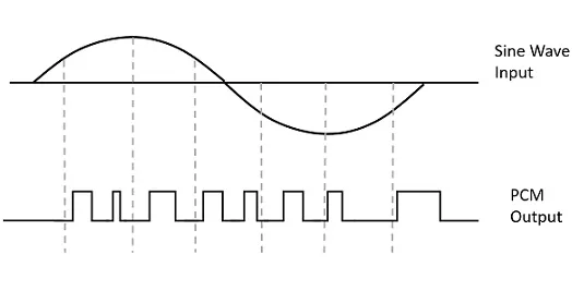
Instead of a pulse train, PCM produces a series of numbers or digits, and hence this process is called as digital. Each one of these digits, though in binary code, represent the approximate amplitude of the signal sample at that instant.
In Pulse Code Modulation, the message signal is represented by a sequence of coded pulses. This message signal is achieved by representing the signal in discrete form in both time and amplitude.
Basic Elements of PCM
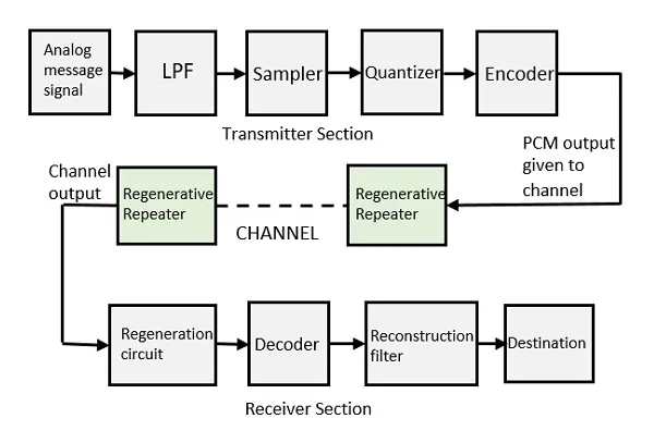
The transmitter section of a Pulse Code Modulator circuit consists of Sampling, Quantizing and Encoding, which are performed in the analog-to-digital converter section. The low pass filter prior to sampling prevents aliasing of the message signal.
The basic operations in the receiver section are regeneration of impaired signals, decoding, and reconstruction of the quantized pulse train. Following is the block diagram of PCM which represents the basic elements of both the transmitter and the receiver sections.
Low Pass Filter
This filter eliminates the high frequency components present in the input analog signal which is greater than the highest frequency of the message signal, to avoid aliasing of the message signal.
Sampler
This is the technique which helps to collect the sample data at instantaneous values of message signal, so as to reconstruct the original signal. The sampling rate must be greater than twice the highest frequency component W of the message signal, in accordance with the sampling theorem.
Quantizer
Quantizing is a process of reducing the excessive bits and confining the data. The sampled output when given to Quantizer, reduces the redundant bits and compresses the value.
Encoder
The digitization of analog signal is done by the encoder. It designates each quantized level by a binary code. The sampling done here is the sample-and-hold process. These three sections LPF,Sampler,andQuantizerLPF,Sampler,andQuantizer will act as an analog to digital converter. Encoding minimizes the bandwidth used.
Regenerative Repeater
This section increases the signal strength. The output of the channel also has one regenerative repeater circuit, to compensate the signal loss and reconstruct the signal, and also to increase its strength.
Decoder
The decoder circuit decodes the pulse coded waveform to reproduce the original signal. This circuit acts as the demodulator.
Reconstruction Filter
After the digital-to-analog conversion is done by the regenerative circuit and the decoder, a low-pass filter is employed, called as the reconstruction filter to get back the original signal.
Hence, the Pulse Code Modulator circuit digitizes the given analog signal, codes it and samples it, and then transmits it in an analog form. This whole process is repeated in a reverse pattern to obtain the original signal.