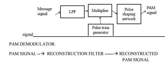
PAM Modulator
The amplitude of a carrier pulse is altered in accordance to that of amplitude of message signal to make it accommodate the information signal.
• Message signal is transmitted to LPF
• LPF performs bandlimiting
• Band limited signal is then sampled at the multiplier.
• Multiplier samples with the help of pulse train generator
• Pulse train generator produces the pulse train
• The multiplication of message signal and pulse train produces PAM
Pulse width modulation
In PWM system, the message signals are used to vary the duration of carrier pulse. The message signal may vary either the trailing edge or leading edge or both of the carrier pulses n order to accommodate the intelligence of information system.
Width of pulse is proportional to the amplitude of the modulating signal.The amplitude and position of the pulse remains unchanged.
PWM Modulator
• It is basically a monostablemultivibrator with message signal applied at the control voltage input.
• Externally applied modulating signal changes the control voltage and hence the threshold voltage level
• The time period required to charge the capacitor upto threshold level changes giving pulse modulated signal
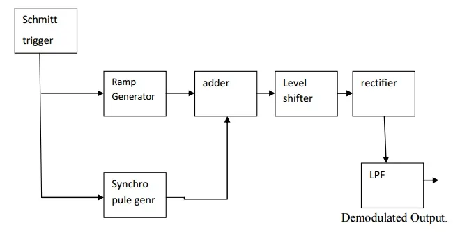
PWM demodulator
PPM Modulator
• Sawtooth generator generates sawtooth signal of frequency which is applied to inverting input of comparator
• Modulating signal is applied to the non-inverting input of comparator
• When the value of message signal is higher than value of sawtooth ,then the output is high
• When the value of message signal is lower than value of sawtooth ,then the output is high.
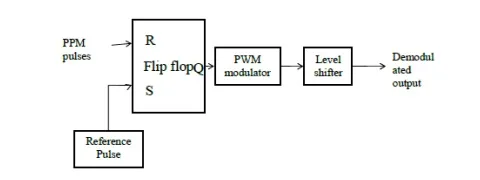
PPM demodulator
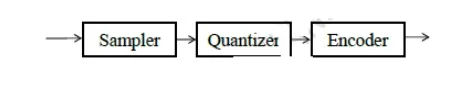
PULSE CODE MODULATION:
Pulse code modulation refers a form of source coding. It is a form of digital modulation techniques in which the code refers a binary word that represent digital data.With PCM, the pulses are of fixed length and fixed amplitude.
Block Diagram of Transmitter
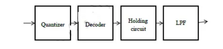
Block Diagram of Receiver
Pulse position modulation
The position of a carrier pulse is altered in accordance with information contained in sampled waveform.
Sampling rate
The sampling rate fs must be atleast two times the highest frequency component of the
original signal to be accurately represented fs>=2fm
Baseband signal receiver.
A baseband signal receiver increases the signal to noise at the instant of sampling.
This reduces the probability of error. The baseband signal receiver is also called optimum receiver.
Matched filter.
The matched filter is a baseband signal receiver, which works in presence of white
Gaussian noise. The impulse response of the matched filter is matched to the shape of the input signal.
The impulse response of matched filter
Impulse response is given as,
h (t) = [2k/ N0 ]{x1 (T − t)}
Here T is the period of sampling x1 (t) and x2 (t) are the two signals used for transmission.
The value of maximum signal to noise ratio of the matched filter
Maximum signal to noise ratio of the matched filter is the ratio of energy of the signal to psd of white noise.
Correlator: It is the coherent receiver. It correlates the received noisy signal f (t) withthe locally generated replica of the known signal x (t). Its output is given as,
r (t) = 0DT f (t) x(t) dt
Matched filter and correlator are functionally same.
The advantages of QPSK as compared to BPSK
1. For the same bit error rate, the bandwidth required by QPSK Is reduced to half as compared to BPSK.
2. Because of reduced bandwidth, the information transmission rate of QPSK is higher.
3. Variation in QPSK amplitude is not much. Hence carrier power almost remains constant.