
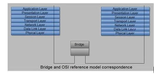
Bridges are connection devices between networks that operate in the data link layer of the OSI model. It means that bridges have more functionality (in terms of connection) than Layer 1 devices, such as repeaters and hubs. Bridges are used to segment networks that have grown to a point where data traffic through the physical environment of the network slows down the global transfer of information.
Like repeaters, bridges are used to connect similar LANs together, for example, Ethernet-to-Ethernet and operate at the bottom two layers of the OSI model, i.e. physical layer and data link layer. As it operates on second layer of the OSI model,’ it relays only necessary data to other signals. MAC addresses (physical addresses) are used to determine whether data is necessary or not.
Bridges (which usually include bridge hardware and some bridge operating system software) can examine MAC addresses (also called hardware addresses; these recorded in the NIC of each computer on the network) in each data packet that circulates through the segments of the network that connects the bridge. By knowing which MAC addresses reside in each of the segments of the network, the bridge can prevent data traffic from a specific segment from passing to another segment of the network that also connected to the bridge.
It passes information from one LAN segment to another based on the destination address of the packet. In other words, when a bridge receives data through one of its ports, it checks the data for a MAC address. If this address matches that of the node connected to other port, the bridge sends this data through this port. This action is called forwarding. If the address does not match with any node connected to other port, the bridge discards it. This action is called filtering. Unlike repeaters, bridges have buffers to store and forward packets in the event that the destination link is congested with traffic.
Therefore, bridges offer a segmentation strategy to recover and preserve bandwidth in a broad homogeneous network (by homogeneous, we mean a network that only uses a defined network architecture, such as Ethernet). For example, a broad network can be divided into three distinct segments using a bridge.
Bridges divide broad networks into segments to keep data traffic between segments isolated.
Although installing a bridge between networks may seem the definitive answer to maximize the adequate performance of the network, the truth is that it has some disadvantages. The bridges send the broadcast packets from the different nodes of the network to all segments of the network (such as NETBIOS and other systems). Also, in those cases in which the bridge cannot resolve a MAC address for a particular segment of the network, it sends the packets to all the segments it connects.
Transparent bridges build a routing table.
Transparent bridges are used in Ethernet networks to forward packets (and isolate those that are part of the local segment traffic) in the network according to a routing table. The bridge constructs this table by creating samples of the packets received at its different ports until a complete list of the MAC addresses of the network and the particular network segment in which they located obtained.
Bridges with the routing of origin
Bridges with source routing in Token Ring networks do not offer as many features as transparent bridges in Ethernet networks. Bridges with source routing receive packets that specify the route that those packets should follow. The bridge has to read the address that each package includes to re-issue it to the corresponding segment.
The main advantage of bridge over repeater is that it has filtering action. If any noise on Ethernet occurs because of collision or disturbance in electrical signal, the bridge will consider it as an incorrectly formed frame and win not forward to the segment connected to other port of the bridge. Note that bridge can relay broadcast packets and packets with unknown destination.
So far, we have seen that at the maximum four repeaters can be used to connect multiple Ethernet segments. However, if a bridge is provided between repeaters, this limit of four is increased. The maximum number of bridges is not specifically limited.
From architecture point of view bridges are protocol independent devices and are very simple. They do not perform complex processes on the data packets traveling through them such as the evaluation of the network as a whole in order to make end-to-end routing decisions. They simply read the destination address of the incoming data packet and forward it along its way to the next link. Therefore, bridges are Inexpensive and fast. There are bridges called cascading bridges, and are used to support multiple LANs connected by multiple media.
Dissimilar LANs such as Ethernet-to-token ring can also be connected with the help of bridge known as encapsulating bridge. The function of encapsulating bridge is also very simple. It encapsulates the originating LAN data along with control information of the end user LAN. Bridges with routing function between LANs are also available.
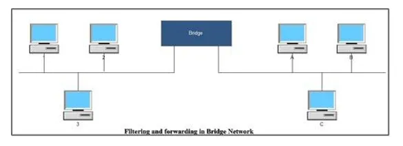
Computer 1 wishes to talk to computer 3 on the same network. The packet sent by computer 1 will contain the physical address of computer 3 that will also be received by the bridge device connecting the two LAN segments. The bridge will read the physical address contained in the packet and observe that this address belongs to the computer on the same LAN segment. Hence, bridge will filter this packet and will not allow it to be transmitted on other side of the network. In case computer 1 wishes to talk with computer C on other segment, the bridge will know from its table of addresses that this address belongs to the computer attached to other segment of the network. In this case this will be forwarded to the other segment of the LAN. The bridge learns location of computers attached the network by watching frames. This will be explained liter on in the subsequent discussion. Note that case of broadcast and multicast packets, bridge forwards these packets to all computers attached to the segment on both sides.
Media Access Control (MAC) Bridge
This is used to connect dissimilar LANs such as Ethernet -to-token ring using encapsulation or translation. This bridge translates the original’ packet format from the requesting LAN segment by encapsulating or enveloping with control data specific to the protocol of the destination LAN segment.
Address Table
As explained above, each bridge should have an address table that indicates the location of different computers or nodes on the segments of LAN. More specifically, it indicates the connection between nodes and ports. When a bridge is booted first time, this table is found to be blank. Now, this question arises how this table is filled with appropriate addresses of different nodes attached to ports. Most of the bridges are called adaptive or self-leaning bridges because they learn the location of the node and associated port themselves and make a list of nodes attached to each segment.
When a bridge receives a data packet from a computer, it first copies the physical address of that computer contained in the packet into its list. Afterward, bridge determines whether this packet should be forwarded or not. In other words, the bridge learns the location of the computer on the network as soon as the computer on the network sends some packet.
If a computer does not send a packet, the bridge will never be able to determine its position and unnecessarily forward the packet on network. Fortunately, this cannot happen because a computer with network software attached to a network transmits at least one frame when the system first boots. Furthermore, computer communication being bidirectional, there is always an acknowledgement for each received packets,
Bridge Protocols
Bridge protocols include spanning tree, source routing protocol, and source routing transparent.
Spanning Tree Protocol (STP) Bridge
This is also known as adaptive or self-learning bridges and is defined in IEEE 802.1 standards. It has already been explained in the above section. Ideally, in bridged network, the network tree of the bridge provides only one span (link) for each LAN-to-LAN connection and therefore, no network with bridges can form a loop. Sometimes, looping can occur.
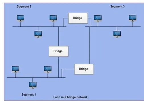
A broadcast data packet sent by the computer attached on segment 1can reach to all computers attached on segment 2 and 3 without a connection between segment 1 and 3 .Sometimes, the bridge connection between segment 1and 3 or like is provided to give the network more redundancy. Now, in this case the same broadcast packet sent by the segment 1 will reach to segment 3 by two routes i.e. from segment 1 to 2 to 3 and another by segment 1 to 3. In this manner the computers on segment 3 will receive duplicate packets. In case of large networks some segments may receive many packets and thus cause looping.
A loop, therefore, can cause a broadcast packet or a packet with an unknown destination to circulate through it, thus rendering the network inoperable. This condition is avoided by making some bridges not to forward frames. An algorithm known as distributed spanning tree (DST) accomplishes this task. This algorithm decides which bridge should forward the packets in the network. Under this scheme bridges exchange a control message known as a hello message to select a single transmission route. Remaining bridges maintain a standby position and provide alternate path in case of the same bridge fails in the selected transmission path. Bridge connecting segment 1 and 3 will be active only if the bridge connecting segment 2 and 3 fails otherwise it acts as a standby bridge for network. In other words, bridges that support the spanning tree algorithm have the ability to automatically reconfigure themselves for alternate paths if a network segment fails, thereby improving overall reliability.
IBM Source Routing Protocol (SRP) Bridge
These are programmed with specific routes for each packet based on considerations such as the physical location of the nodes, and the number of bridges involved.
Source Routing Transparent (SRT)
It is defined in theIEEE802.1 standard. It is effectively a combination of STP and SRP. The SRT router can connect LANs by either method, as programmed.
Classification of Bridges
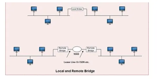
These are classified into local and remote bridges:
· 1. Local bridges are ordinary bridges
· 2. Remote bridges are used to connect networks that are far from each other. A WAN is generally provided between two bridges.
Figure shows the local and remote bridge connection.

Comments are closed