We are talking of Wireless LAN (WLAN) that is to say, “Wireless LAN”, not to be confused with WAN course. Also referred Radio LAN (WLAN) if the communication medium is the radio (not light infrared for example).The stations of the wireless network can communicate directly with each other, we called Ad Hoc network type, or via relay terminals called APs (Access Points, PA) then it is an infrastructure network. the second type is by far the most common in business.
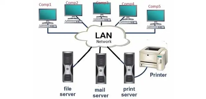
The wired LAN provides reliable service to users, working in a fixed environment. Once installed, the workstations and the servers of a wired LAN are fixed in their native locations. For users who are highly mobile or in a rough terrain, where there is no possibility to install and lay down the cables of a wired LAN, a good solution is to install a wireless LAN. Wireless LANs transmit and receive data over the atmosphere, using radio frequency (RF) or infrared optical technology, there by, eliminating the need for fixed wired connections. Wireless LANs provides dual advantage of connectivity and mobility. Wireless LANs have gained strong popularity in applications like health-care, retail, manufacturing, warehousing, and academic. These applications use hand-held terminals and notebook computers to transmit real-time information to centralized ‘hosts’ for processing. Figure shows simple wired and wireless networks.
Wireless LANs have limitations when compared with wired LANs. Wireless LANs are slower than wired LAN. Also, they have limitations with their range of operation. When a station is moved out of its range, it suffers from noise and error in the received data due to the poor signal strength.
IEEE formed a working group to develop a Medium Access Control (MAC) and Physical Layer (PHY) standard for wireless connectivity for stationary, portable, and mobile computers within a local area. This working group is IEEE 802.11. The recommendations of the 802.11 committee have become the standard for wireless networking.
Need for Wireless LANs
Networking and Internet services are essential requirements for today’s business computing. An increasing number of LAN users are becoming mobile. These mobile users require connectivity to a network, regardless of where they are because they want simultaneous access to the network. With wireless LANs, users can access shared information without looking for a place to plug in their systems and do not need network managers to set up networks to install cable and other equipment.
Advantages of Wireless LANs
Wireless LANs offer the following advantages over traditional wired networks. Mobility Users on a wireless LAN systems can access to real-time information from anywhere within their organization. This mobility supports productivity and service opportunities, which are not possible with wired networks.
Fast Installation and Simplicity: Installing a wireless LAN system can be fast and easy and can eliminate the need to pull cables through walls, floor, and ceilings.
Installation Flexibility: Wireless network is suitable for any kind of geographical conditions. Installation requires to properly setup the transmitter and the receiver antenna (RF) or infrared system. This is much easier than cable installation of a wired LAN. If a company decided to move to a new location, the wireless system is much easier to move.
Reduced Cost: The initial investment required for wireless LAN hardware is higher than the cost of wired LAN hardware. However, the overall installation expenses and life cycle costs are significantly lower. Long-term cost benefits are greatest in dynamic environments, requiring frequent moves and changes.
Scalability Wireless LAN systems can be configured in a variety of topologies to cater to the need for specific applications and installations. Configurations can be easily changed. They scale well. New nodes can be added to the existing wireless LAN without much degradation of performance.
Uses of Wireless LANs
Wireless LANs frequently act as a substitute rather than replacement for a wired LAN network. They often provide the final few meters of connectivity between a wired network and the mobile user. The following list describes some of the many applications made possible through the power and flexibility of wireless LANs:
• Doctors and nurses in hospitals can be more productive because wireless hand-held terminals or notebook computers with wireless LAN capability can deliver patient information instantly.
• Consulting or accounting audit teams or small workgroups can increase the productivity with quick wireless network setup.
• Students or research scholars, attending a class inside an institute campus can instantly access the Internet to consult the catalog of the net digital library.
• Network managers in dynamic environments minimize the overhead caused by moves, extensions to networks, and other changes with wireless LANs.
• Training sites at corporations and students at universities use wireless connectivity to ease access to information, information exchanges, and learning.
• Network managers installing networked computers in older buildings find that wireless LANs are a cost-effective network infrastructure solution.
• Travelers and tourists can book their ticket through the net during their travel.
• Warehouse workers use wireless LANs to exchange information with central databases.
• Network managers implement wireless LANs to provide backup for mission-critical applications, running on wired networks.
• Senior executives in meetings make quicker decisions because they have real-time information at their fingertips.
Component of a Wireless LAN
Apart from the components needed by the conventional wired LAN, a wireless LAN needs additional components. They are the transmitters and receivers at radio frequency (RF) or infrared (IR). The RF transmitter and receivers need antennas to perform two-way communication. This area requires a wide knowledge about antenna and propagation. Usually a trial installation is carried out before actual implementation. Hubs, bridges, network operating system, servers, and other components are functioning exactly as they were, on a wired LAN.
Mobile Clients
Mobile clients are portable computing devices that act as clients. The following are some of the mobile systems.
1. Laptop computers: Laptop PCs with two-way communication facility (Transceiver)
2. Palmtops or Personal Digital Assistants (PDA) with communication capability
3. Portable FAX
4. Cellular phones
Special Units
For network management and efficient communication, a wireless LAN needs additional equipments.
They are:
Communication units: These units perform communications within the network and also with other networks.
Data collecting units: These units collect data from other systems.
Security Units: These units take care of the network security.
Transceivers: A transceiver is a half-duplex device. It performs transmission and reception of data within a wireless LAN. It can be able to transmit in one direction at a time.
Portable bridges: Portable Bridge can support internet working functions. Two wireless LANs can communicate with each other using a bridge. It can be a transceiver or a satellite port or other communication unit that provides a bridge service.
Working of Wireless LANs
Wireless LANs use electromagnetic waves (radio or infrared technology) to communicate information from one point to another without relying on any physical connection. Radio waves are often referred as radio carriers because they simply perform the function of delivering energy to a remote receiver. The data being transmitted is superimposed on the radio carrier so that it can be accurately extracted at the receiving end. This is generally referred to as modulation of the carrier by the information being transmitted. Once data is superimposed (modulated) onto the radio carrier, the radio signal occupies more than a single frequency, since the frequency or bit rate of the modulating information adds to the carrier. Multiple radio carriers can exist in the same space at the same time without interfering with each other if the radio waves are transmitted on different radio frequencies. To extract data, a radio receiver tunes in one radio frequency while rejecting all other frequencies. In a typical wireless LAN configuration, a transmitter/receiver (transceiver) device, called an access point, connects to the wired network from a fixed location, using standard cabling. The access point receives, buffers, and retransmits data between the wireless LAN and the wired network infrastructure. A single access point can support a small group of users and can function within a range of less than one hundred to several hundred feet. The access point (or the antenna attached to the access point) is usually mounted high but may be mounted essentially anywhere that is practical as long as the desired radio coverage is obtained.
End users access the wireless LAN through wireless LAN adapters, which are implemented as add-on cards in notebook or palmtop computers, as cards in desktop computers, or integrated within hand-held computers. Wireless LAN adapters provide an interface between the client network operating system (NOS) and the airwaves via an antenna. The nature of the wireless connection is transparent to the NOS.
There are two types of wireless networks:
• Type networks Ad Hoc, where stations communicate directly;
• Infrastructure type networks where stations communicate through access points.
To communicate, each station must of course be equipped with an adapter WiFi and a radio antenna (often integrated into the adapter). More and more computer equipment come with a built-in WiFi adapter. Except not the case, you must buy one and connect it to the station. The connection is very varied: there are WiFi USB adapters, PCMCIA, PCI, etc.
There are several variations of WiFi. In short, 802.11b and 802.11g are compatible them and both operate with the radio waves of a frequency of 2.4 GHz. The 802.11b reached a speed of 11 Mb / s and 802.11g rises to 54 Mb / s. The 802.11a is not compatible with 802.11b and 802.11g, because it works with the waves a radio frequency of 5 GHz. It can reach 54 Mb / s. The 802.11n allows to achieve a real flow rate greater than 100 Mb / s. It is capable of operating at 2.4 GHz or 5 GHz and is compatible with the 802.11b / g and 802.11a. Unfortunately, Most 802.11n equipment available today use only tape 2.4 GHz (and are therefore not compatible with the 802.11a).
Today the WiFi version of the most used is far 802.11g. It should be rapidly overtaken by 802.11n.
The fact that WiFi is originally designed to perform WLAN does not prevent not also be used in other contexts. For example, a myriad of products, such as electronic organizers (PDAs) or Personal Data Assistant (PDAs), printers, computer monitors, VCRs or even Hi-Fi, are now equipped with WiFi connections allowing them to be linked together without any wire. In this case, the WLAN is used to achieve a WPAN. Conversely, many local authorities do not have access to top speed (ADSL is not available everywhere) are turning to WiFi to cover a town or towns with the same wireless network. This can be called Wireless MAN (WMAN).
Finally, companies are deploying wireless networks, called hotspots1 that allow anyone to connect to the Internet wirelessly slightly across the US and around the world. So one sees now what might be called WWAN (Wireless Wide Area Networks) based on WiFi technology (WiFi technology itself, however, carries data over short distances).
802.11 Architecture
The 802.11architecture defines two types of services and three different types of stations
802.11 Services
The two types of services are
1. Basic services set (BSS)
2. Extended Service Set (ESS)
1. Basic Services Set (BSS)
• The basic services set contain stationary or mobile wireless stations and a central base station called access point (AP).
• The use of access point is optional.
• If the access point is not present, it is known as stand-alone network. Such a
BSS cannot send data to other BSSs. This type of architecture is known as adhoc architecture.
• The BSS in which an access point is present is known as an infrastructure network.

2. Extend Service Set (ESS)
• An extended service set is created by joining two or more basic service sets (BSS) having access points (APs).
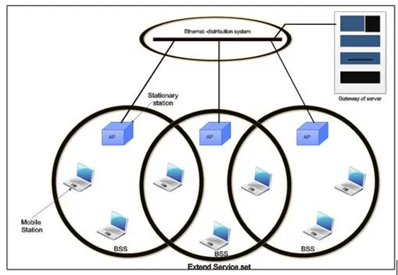
• These extended networks are created by joining the access points of basic services sets through a wired LAN known as distribution system.
• The distribution system can be any IEET LAN.
• There are two types of stations in ESS:
(i) Mobile stations: These are normal stations inside a BSS.
(ii) Stationary stations: These are AP stations that are part of a wired LAN.
• Communication between two stations in two different BSS usually occurs via two APs.
• A mobile station can belong to more than one BSS at the same time.
802.11 Station Types
IEEE 802.11 defines three types of stations on the basis of their mobility in wireless LAN. These are:
1. No-transition Mobility
2. BSS-transition Mobility
3. ESS-transition Mobility
1. No-transition .Mobility: These types of stations are either stationary i.e. immovable or move only inside a BSS.
2. BSS-transition mobility: These types of stations can move from one BSS to another but the movement is limited inside an ESS.
3. ESS-transition mobility: These types of stations can move from one ESS to another. The communication mayor may not be continuous when a station moves from one ESS to another ESS.
Physical layer functions
• As we know that physical layer is responsible for converting data stream into signals, the bits of 802.11 networks can be converted to radio waves or infrared waves.
• These are six different specifications of IEEE 802.11. These implementations, except the first one, operate in industrial, scientific and medical (ISM) band. These three banks are unlicensed and their ranges are
1.902-928 MHz
2.2.400-4.835 GHz
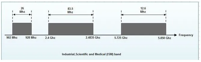
3.5.725-5.850 GHz
• The different implementations of IEE802.11 are given below:
1. IEEE 802.11 infrared
• It uses diffused (not line of sight) infrared light in the range of 800 to 950 nm.
• It allows two different speeds: I Mbps and 2Mbps.
• For a I-Mbps data rate, 4 bits of data are encoded into 16 bit code. This 16 bit code contains fifteen as and a single 1.
• For a 2-Mbps data rate, a 2 bit code is encoded into 4 bit code. This 4 bit code contains three Os and a single 1.
• The modulation technique used is pulse position modulation (PPM) i.e. for converting digital signal to analog.
2. IEEE 802.11 FHSS
• IEEE 802.11 uses Frequency Hoping Spread Spectrum (FHSS) method for signal generation.
• This method uses 2.4 GHz ISM band. This band is divided into 79 subbands of 1MHz with some guard bands.
• In this method, at one moment data is sent by using one carrier frequency and then by some other carrier frequency at next moment. After this, an idle time is there in communication. This cycle is repeated after regular intervals.
• A pseudo random number generator selects the hopping sequence.
• The allowed data rates are 1 or 2 Mbps.
• This method uses frequency shift keying (two level or four level) for modulation i.e. for converting digital signal to analogy.
3. IEEE 802.11 DSSS
• This method uses Direct Sequence Spread Spectrum (DSSS) method for signal generation. Each bit is transmitted as 11 chips using a Barker sequence.
• DSSS uses the 2.4-GHz ISM band.
• It also allows the data rates of 1 or 2 Mbps.
• It uses phase shift keying (PSK) technique at 1 M baud for converting digital signal to analog signal.
4. IEEE 802.11a OFDM
• This method uses Orthogonal Frequency Division Multiplexing (OFDM) for signal generation.
• This method is capable of delivering data upto 18 or 54 Mbps.
• In OFDM all the subbands are used by one source at a given time.
• It uses 5 GHz ISM band.
• This band is divided into 52 subbands, with 48 subbands for data and 4 subbands for control information.
• If phase shift keying (PSK) is used for modulation then data rate is 18 Mbps. If quadrature amplitude modulation (QAM) is used, the data rate can be 54 Mbps.
5. IEEE 802.11b HR-OSSS
• It uses High Rate Direct Sequence Spread Spectrum method for signal generation.
• HR-DSSS is similar to DSSS except for encoding method.
• Here, 4 or 8 bits are encoded into a special symbol called complementary code key (CCK).
• It uses 2.4 GHz ISM band.
• It supports four data rates: 1,2,5.5 and 11 Mbps.
• 1 Mbps and 2 Mbps data rates uses phase shift modulation.
• The 5.5. Mbps version uses BPSK and transmits at 1.375 Mbaud/s with 4-bit CCK encoding.
• The 11 Mbps version uses QPSK and transmits at 1.375 Mbps with 8-bit CCK encoding.
6. IEEE 802.11g OFDM
• It uses OFDM modulation technique.
• It uses 2.4 GHz ISM band.
• It supports the data rates of 22 or 54 Mbps.
• It is backward compatible with 802.11 b.
MAC sublayer Functions
802.11 support two different modes of operations. These are:
1. Distributed Coordination Function (DCF)
2. Point Coordination Function (PCF)
1. Distributed Coordination Function
• The DCF is used in BSS having no access point.
• DCF uses CSMA/CA protocol for transmission.
• The following steps are followed in this method.
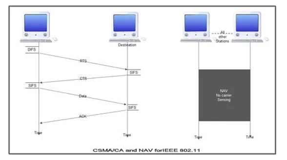
1. When a station wants to transmit, it senses the channel to see whether it is free or not.
2. If the channel is not free the station waits for back off time.
3. If the station finds a channel to be idle, the station waits for a period of time called distributed interframe space (DIFS).
4. The station then sends control frame called request to send (RTS) as shown in figure.
5. The destination station receives the frame and waits for a short period of time called short interframe space (SIFS).
6. The destination station then sends a control frame called clear to send (CTS) to the source station. This frame indicates that the destination station is ready to receive data.
7. The sender then waits for SIFS time and sends data.
8. The destination waits for SIFS time and sends acknowledgement for the received frame.
Collision avoidance
• 802.11 standard uses Network Allocation Vector (NAV) for collision avoidance.
• The procedure used in NAV is explained below:
1. Whenever a station sends an RTS frame, it includes the duration of time for which the station will occupy the channel.
2. All other stations that are affected by the transmission creates a timer caned network allocation vector (NAV).
3. This NAV (created by other stations) specifies for how much time these stations must not check the channel.
4. Each station before sensing the channel, check its NAV to see if has expired or not.
5. If its NA V has expired, the station can send data, otherwise it has to wait.
• There can also be a collision during handshaking i.e. when RTS or CTS control frames are exchanged between the sender and receiver. In this case following procedure is used for collision avoidance:
1. When two or more stations send RTS to a station at same time, their control frames collide.
2. If CTS frame is not received by the sender, it assumes that there has been a collision.
3. In such a case sender, waits for back off time and retransmits RTS.
2. Point Coordination Function
• PCF method is used in infrastructure network. In this Access point is used to control the network activity.
• It is implemented on top of the DCF and IS used for time sensitive transmissions.
• PCF uses centralized, contention free polling access method.
• The AP performs polling for stations that wants to transmit data. The various stations are polled one after the other.
• To give priority to PCF over DCF, another interframe space called PIFS is defined. PIFS (PCF IFS) is shorter than DIFS.
• If at the same time, a station is using DCF and AP is using PCF, then AP is given priority over the station.
• Due to this priority of PCF over DCF, stations that only use DCF may not gain access to the channel.
• To overcome this problem, a repetition interval is defined that is repeated continuously. This repetition interval starts with a special control frame called beacon frame.
• When a station hears beacon frame, it start their NAV for the duration of the period of the repetition interval.
Frame Format of 802.11
The MAC layer frame consists of nine fields.
1. Frame Control (FC). This is 2 byte field and defines the type of frame and some control information. This field contains several different subfields.
These are listed in the table below: 
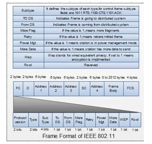
2. D. It stands for duration and is of 2 bytes. This field defines the duration for which the frame and its acknowledgement will occupy the channel. It is also used to set the value of NA V for other stations.
3. Addresses. There are 4 address fields of 6 bytes length. These four addresses represent source, destination, source base station and destination base station.
4. Sequence Control (SC). This 2 byte field defines the sequence number of frame to be used in flow control.
5. Frame body. This field can be between 0 and 2312 bytes. It contains the information.
6. FCS. This field is 4 bytes long and contains ‘cRC-32 error detection sequence.
IEEE 802.11 Frame types
There are three different types of frames:
1. Management frame
2. Control frame
3. Data frame
1. Management frame. These are used for initial communication between stations and access points.
2. Control frame. These are used for accessing the channel and acknowledging frames. The control frames are RTS and CTS.
3. Data frame. These are used for carrying data and control information.
802.11 Addressing
• There are four different addressing cases depending upon the value of To DS And from DS subfields of FC field.
• Each flag can be 0 or 1, resulting in 4 different situations.
1. If To DS = 0 and From DS = 0, it indicates that frame is not going to distribution system and is not coming from a distribution system. The frame is going from one station in a BSS to another.
2. If To DS = 0 and From DS = 1, it indicates that the frame is coming from a distribution system. The frame is coming from an AP and is going to a station. The address 3 contains original sender of the frame (in another BSS).
3. If To DS = 1 and From DS = 0, it indicates that the frame is going to a distribution system. The frame is going from a station to an AP. The address 3 field contains the final destination of the frame.
4. If To DS = 1 and From DS = 1,it indicates that frame is going from one AP to another AP in a wireless distributed system.
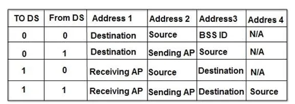
The table below specifies the addresses of all four cases.
Protocols for Wireless LAN
The CSMA protocol is very difficult to implement for wireless LAN. Hence special protocols are needed to avoid collision. MACA and MACAW are the two widely used protocols.
MACA Protocol
During 1990, Kam developed the MACA (Multiple Access with Collision Avoidance) protocol for wireless transmission. The protocol is very simple to implement and works in the following manner. Station X, willing to transmit data to the nearby station Y, sends a short frame called RTS (Request to Send) first. On hearing this short frame, all stations other than the receiving station, avoid transmission, thereby allowing the communication to take place without interference. The receiving station sends a CTS (Clear to Send) frame to the calling station. After receiving the CTS frame, station X begins transmission. When simultaneous transmission of RTS by two stations Wand X to station Y occurs, both frames collide with each other and are lost. When there is no CTS from station Y, both stations wait for a random amount of time (binary exponential back off) and start the whole process again.
MACAW Protocol
Bhargavan et al (1994) investigated the behavior of MACA protocol and refined it with modifications. The first modification was the acknowledgment frame for the successful receipt of each frame. This modification adds carrier sense to stations. The second modification was to apply the binary exponential back off algorithm to source-destination pair. This improves the fairness of the protocol. They have also added to stations, the ability to exchange information, regarding congestion.