Amplitude Shift Keying ASKASK is a type of Amplitude Modulation which represents the binary data in the form of variations in the amplitude of a signal.
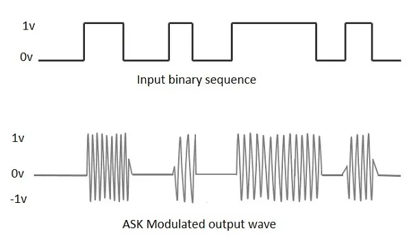
Any modulated signal has a high frequency carrier. The binary signal when ASK modulated, gives a zero value for Low input while it gives the carrier output for High input.
The following figure represents ASK modulated waveform along with its input.
To find the process of obtaining this ASK modulated wave, let us learn about the working of the ASK modulator.
ASK Modulator
The ASK modulator block diagram comprises of the carrier signal generator, the binary sequence from the message signal and the band-limited filter. Following is the block diagram of the ASK Modulator.
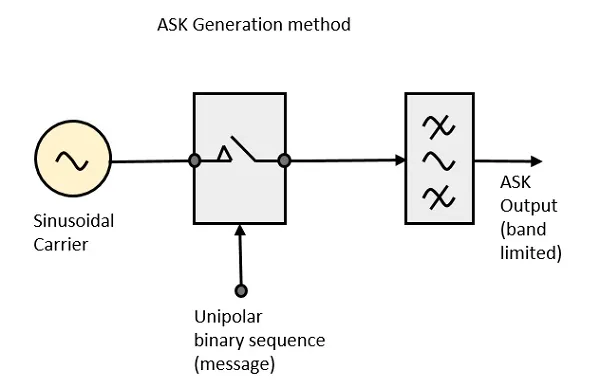
The carrier generator, sends a continuous high-frequency carrier. The binary sequence from the message signal makes the unipolar input to be either High or Low. The high signal closes the switch, allowing a carrier wave. Hence, the output will be the carrier signal at high input. When there is low input, the switch opens, allowing no voltage to appear. Hence, the output will be low.
The band-limiting filter, shapes the pulse depending upon the amplitude and phase characteristics of the band-limiting filter or the pulse-shaping filter.
ASK Demodulator
There are two types of ASK Demodulation techniques. They are −
- Asynchronous ASK Demodulation/detection
- Synchronous ASK Demodulation/detection
The clock frequency at the transmitter when matches with the clock frequency at the receiver, it is known as a Synchronous method, as the frequency gets synchronized. Otherwise, it is known as Asynchronous.
Asynchronous ASK Demodulator
The Asynchronous ASK detector consists of a half-wave rectifier, a low pass filter, and a comparator. Following is the block diagram for the same.
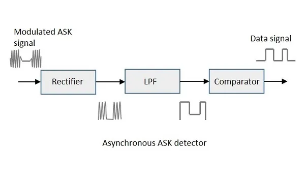
The modulated ASK signal is given to the half-wave rectifier, which delivers a positive half output. The low pass filter suppresses the higher frequencies and gives an envelope detected output from which the comparator delivers a digital output.
Synchronous ASK Demodulator
Synchronous ASK detector consists of a Square law detector, low pass filter, a comparator, and a voltage limiter. Following is the block diagram for the same.
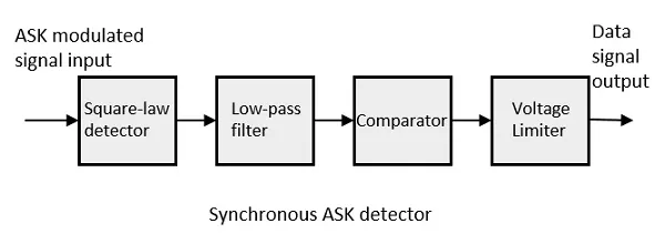
The ASK modulated input signal is given to the Square law detector. A square law detector is one whose output voltage is proportional to the square of the amplitude modulated input voltage. The low pass filter minimizes the higher frequencies. The comparator and the voltage limiter help to get a clean digital output.