
Software architecture involves the high level structure of software system abstraction, by using decomposition and composition, with architectural style and quality attributes. A software architecture design must conform to the major functionality and performance requirements of the system, as well as satisfy the non-functional requirements such as reliability, scalability, portability, and availability.
A software architecture must describe its group of components, their connections, interactions among them and deployment configuration of all components.
A software architecture can be defined in many ways −
· UML (Unified Modeling Language) − UML is one of object-oriented solutions used in software modeling and design.
· Architecture View Model (4+1 view model) − Architecture view model represents the functional and non-functional requirements of software application.
· ADL (Architecture Description Language) − ADL defines the software architecture formally and semantically.
UML
UML stands for Unified Modeling Language. It is a pictorial language used to make software blueprints. UML was created by Object Management Group (OMG). The UML 1.0 specification draft was proposed to the OMG in January 1997. It serves as a standard for software requirement analysis and design documents which are the basis for developing a software.
UML can be described as a general purpose visual modeling language to visualize, specify, construct, and document a software system. Although UML is generally used to model software system, it is not limited within this boundary. It is also used to model non software systems such as process flows in a manufacturing unit.
The elements are like components which can be associated in different ways to make a complete UML picture, which is known as a diagram. So, it is very important to understand the different diagrams to implement the knowledge in real-life systems. We have two broad categories of diagrams and they are further divided into sub-categories i.e. Structural Diagrams and Behavioral Diagrams.
Structural Diagrams
Structural diagrams represent the static aspects of a system. These static aspects represent those parts of a diagram which forms the main structure and is therefore stable. These static parts are represented by classes, interfaces, objects, components and nodes.
The structural diagrams are sub-divided as (shown in the following image) −
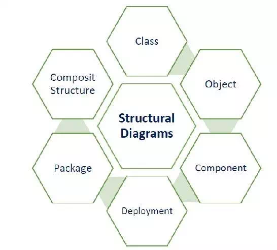
The following table provides a brief description of these diagrams −
| Diagram | Description |
| Class | Represents the object orientation of a system. Shows how classes are statically related. |
| Object | Represents a set of objects and their relationships at runtime and also represent the static view of the system. |
| Component | Describes all the components, their interrelationship, interactions and interface of the system. |
| Composite structure | Describes inner structure of component including all classes, interfaces of the component, etc. |
| Package | Describes the package structure and organization. Covers classes in the package and packages within another package. |
| Deployment | Deployment diagrams are a set of nodes and their relationships. These nodes are physical entities where the components are deployed. |
Behavioral Diagrams
Behavioral diagrams basically capture the dynamic aspect of a system. Dynamic aspects are basically the changing/moving parts of a system. UML has the following types of behavioral diagrams (shown in the image given below) −
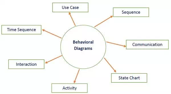
The following table provides a brief description of these diagram −
| Diagram | Description |
| Use case | Describes the relationships among the functionalities and their internal/external controllers. These controllers are known as actors. |
| Activity | Describes the flow of control in a system. It consists of activities and links. The flow can be sequential, concurrent, or branched. |
| State Machine/state chart | Represents the event driven state change of a system. It basically describes the state change of a class, interface, etc. Used to visualize the reaction of a system by internal/external factors. |
| Sequence | Visualizes the sequence of calls in a system to perform a specific functionality. |
| Interaction Overview | Combines activity and sequence diagrams to provide a control flow overview of system and business process. |
| Communication | Same as sequence diagram, except that it focuses on the object’s role. Each communication is associated with a sequence order, number plus the past messages. |
| Time Sequenced | Describes the changes by messages in state, condition and events. |
Architecture View Model
A model is a complete, basic, and simplified description of software architecture which is composed of multiple views from a particular perspective or viewpoint.
A view is a representation of an entire system from the perspective of a related set of concerns. It is used to describe the system from the viewpoint of different stakeholders such as end-users, developers, project managers, and testers.
4+1 View Model
The 4+1 View Model was designed by Philippe Kruchten to describe the architecture of a software–intensive system based on the use of multiple and concurrent views. It is a multiple view model that addresses different features and concerns of the system. It standardizes the software design documents and makes the design easy to understand by all stakeholders.
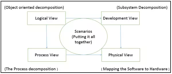
It is an architecture verification method for studying and documenting software architecture design and covers all the aspects of software architecture for all stakeholders. It provides four essential views −
· The logical view or conceptual view − It describes the object model of the design.
· The process view − It describes the activities of the system, captures the concurrency and synchronization aspects of the design.
· The physical view − It describes the mapping of software onto hardware and reflects its distributed aspect.
· The development view − It describes the static organization or structure of the software in its development of environment.
This view model can be extended by adding one more view called scenario view or use case view for end-users or customers of software systems. It is coherent with other four views and are utilized to illustrate the architecture serving as “plus one” view, (4+1) view model. The following figure describes the software architecture using five concurrent views (4+1) model.
Why is it called 4+1 instead of 5?
The use case view has a special significance as it details the high level requirement of a system while other views details — how those requirements are realized. When all other four views are completed, it’s effectively redundant. However, all other views would not be possible without it. The following image and table shows the 4+1 view in detail −
| Logical | Process | Development | Physical | Scenario | |
| Description | Shows the component (Object) of system as well as their interaction | Shows the processes / Workflow rules of system and how those processes communicate, focuses on dynamic view of system | Gives building block views of system and describe static organization of the system modules | Shows the installation, configuration and deployment of software application | Shows the design is complete by performing validation and illustration |
| Viewer / Stake holder | End-User, Analysts and Designer | Integrators & developers | Programmer and software project managers | System engineer, operators, system administrators and system installers | All the views of their views and evaluators |
| Consider | Functional requirements | Non Functional Requirements | Software Module organization (Software management reuse, constraint of tools) | Nonfunctional requirement regarding to underlying hardware | System Consistency and validity |
| UML – Diagram | Class, State, Object, sequence, Communication Diagram | Activity Diagram | Component, Package diagram | Deployment diagram | Use case diagram |
Architecture Description Languages (ADLs)
An ADL is a language that provides syntax and semantics for defining a software architecture. It is a notation specification which provides features for modeling a software system’s conceptual architecture, distinguished from the system’s implementation.
ADLs must support the architecture components, their connections, interfaces, and configurations which are the building block of architecture description. It is a form of expression for use in architecture descriptions and provides the ability to decompose components, combine the components, and define the interfaces of components.
An architecture description language is a formal specification language, which describes the software features such as processes, threads, data, and sub-programs as well as hardware component such as processors, devices, buses, and memory.
It is hard to classify or differentiate an ADL and a programming language or a modeling language. However, there are following requirements for a language to be classified as an ADL −
· It should be appropriate for communicating the architecture to all concerned parties.
· It should be suitable for tasks of architecture creation, refinement, and validation.
· It should provide a basis for further implementation, so it must be able to add information to the ADL specification to enable the final system specification to be derived from the ADL.
· It should have the ability to represent most of the common architectural styles.
· It should support analytical capabilities or provide quick generating prototype implementations.

Comments are closed