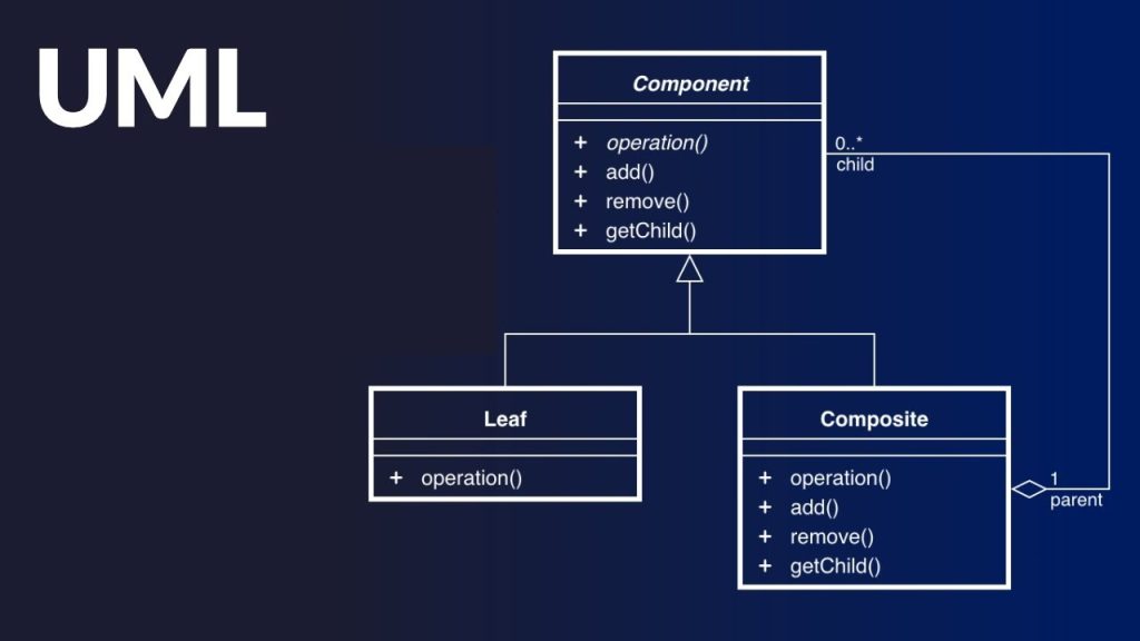
Model
A model captures aspect important for some application while omitting (or abstracting) the rest. A model in the context of software development can be graphical, textual, mathematical, or program code-based. Models are very useful in documenting the design and analysis results. Models also facilitate the analysis and design procedures themselves. Graphical models are very popular because they are easy to understand and construct. UML is primarily a graphical modeling tool. However, it often requires text explanations to accompany the graphical models.
Need for a model
An important reason behind constructing a model is that it helps manage complexity. Once models of a system have been constructed, these can be used for a variety of purposes during software development, including the following:
• Analysis
• Specification
• Code generation
• Design
• Visualize and understand the problem and the working of a system
• Testing, etc
In all these applications, the UML models can not only be used to document the results but also to arrive at the results themselves. Since a model can be used for a variety of purposes, it is reasonable to expect that the model would vary depending on the purpose for which it is being constructed. For example, a model developed for initial analysis and specification should be very different from the one used for design. A model that is being used for analysis and specification would not show any of the design decisions that would be made later on during the design stage. On the other hand, a model used for design purposes should capture all the design decisions. Therefore, it is a good idea to explicitly mention the purpose for which a model has been developed, along with the model.
Unified Modeling Language (UML)
UML, as the name implies, is a modeling language. It may be used to visualize, specify, construct, and document the artifacts of a software system. It provides a set of notations (e.g. rectangles, lines, ellipses, etc.) to create a visual model of the system. Like any other language, UML has its own syntax (symbols and sentence formation rules) and semantics (meanings of symbols and sentences). Also, we should clearly understand that UML is not a system design or development methodology but can be used to document object-oriented and analysis results obtained using some methodology.
Origin of UML
In the late 1980s and early 1990s, there was a proliferation of object-oriented design techniques and notations. Different software development houses were using different notations to document their object-oriented designs. These diverse notations used to give rise to a lot of confusion.
UML was developed to standardize the large number of object-oriented modeling notations that existed and were used extensively in the early 1990s. The principles ones in use were:
• Object Management Technology [Rumbaugh 1991]
• Booch’s methodology [Booch 1991]
• Object-Oriented Software Engineering [Jacobson 1992]
• Odell’s methodology [Odell 1992]
• Shaler and Mellor methodology [Shaler 1992]
It is needless to say that UML has borrowed many concepts from these modeling techniques. Especially, concepts from the first three methodologies have been heavily drawn upon. UML was adopted by Object Management Group (OMG) as a de facto standard in 1997. OMG is an association of industries which tries to facilitate early formation of standards.
We shall see that UML contains an extensive set of notations and suggests construction of many types of diagrams. It has successfully been used to model both large and small problems. The elegance of UML, its adoption by OMG, and a strong industry backing have helped UML find widespread acceptance. UML is now being used in a large number of software development projects worldwide.
UML diagrams
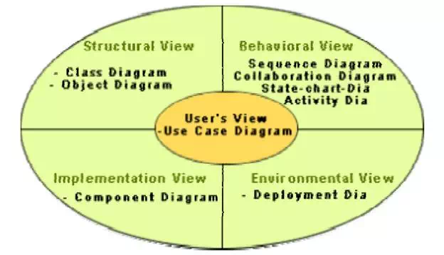
UML can be used to construct nine different types of diagrams to capture five different views of a system. Just as a building can be modeled from several views (or perspectives) such as ventilation perspective, electrical perspective, lighting perspective, heating perspective, etc.; the different UML diagrams provide different perspectives of the software system to be developed and facilitate a comprehensive understanding of the system. Such models can be refined to get the actual implementation of the system.
The UML diagrams can capture the following five views of a system:
• User’s view
• Structural view
• Behavioral view
• Implementation view
• Environmental view
shows the UML diagrams responsible for providing the different views.
Different types of diagrams and views supported in UML
User’s view:
This view defines the functionalities (facilities) made available by the system to its users. The users’ view captures the external users’ view of the system in terms of the functionalities offered by the system. The users’ view is a black-box view of the system where the internal structure, the dynamic behavior of different system components, the implementation etc. are not visible. The users’ view is very different from all other views in the sense that it is a functional model compared to the object model of all other views. The users’ view can be considered as the central view and all other views are expected to conform to this view. This thinking is in fact the crux of any user centric development style.
Structural view:
The structural view defines the kinds of objects (classes) important to the understanding of the working of a system and to its implementation. It also captures the relationships among the classes (objects). The structural model is also called the static model, since the structure of a system does not change with time.
Behavioral view:
The behavioral view captures how objects interact with each other to realize the system behavior. The system behavior captures the time-dependent (dynamic) behavior of the system.
Implementation view:
This view captures the important components of the system and their dependencies.
Environmental view:
This view models how the different components are implemented on different pieces of hardware.