
From use case diagram, it is obvious that the utility of the use cases are represented by ellipses. They along with the accompanying text description serve as a type of requirements specification of the system and form the core model to which all other models must conform. But, what about the actors (stick person icons)? One possible use of identifying the different types of users (actors) is in identifying and implementing a security mechanism through a login system, so that each actor can involve only those functionalities to which he is entitled to. Another possible use is in preparing the documentation (e.g. users’ manual) targeted at each category of user. Further, actors help in identifying the use cases and understanding the exact functioning of the system.
Factoring of use cases
It is often desirable to factor use cases into component use cases. Actually, factoring of use cases are required under two situations. First, complex use cases need to be factored into simpler use cases. This would not only make the behavior associated with the use case much more comprehensible, but also make the corresponding interaction diagrams more tractable. Without decomposition, the interaction diagrams for complex use cases may become too large to be accommodated on a single sized (A4) paper. Secondly, use cases need to be factored whenever there is common behavior across different use cases. Factoring would make it possible to define such behavior only once and reuse it whenever required. It is desirable to factor out common usage such as error handling from a set of use cases. This makes analysis of the class design much simpler and elegant. However, a word of caution here. Factoring of use cases should not be done except for achieving the above two objectives. From the design point of view, it is not advantageous to break up a use case into many smaller parts just for the shake of it.
UML offers three mechanisms for factoring of use cases as follows:
Generalization
Use case generalization can be used when one use case that is similar to another but does something slightly differently or something more. Generalization works the same way with use cases as it does with classes. The child use case inherits the behavior and meaning of the parent use case. The notation is the same too. It is important to remember that the base and the derived use cases are separate use cases and should have separate text descriptions.
Representation of use case generalization 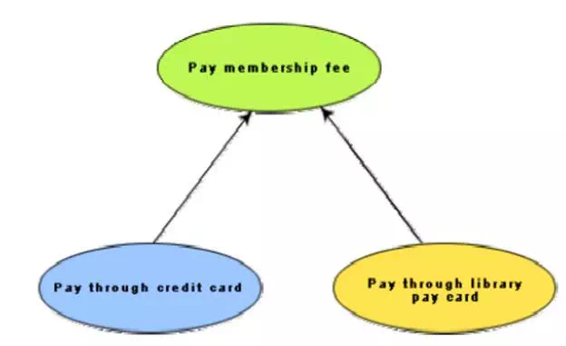
Includes
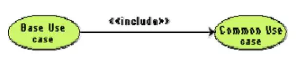
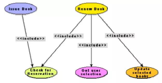
The includes relationship in the older versions of UML (prior to UML 1.1) was known as the uses relationship. The includes relationship involves one use case including the behavior of another use case in its sequence of events and actions. The includes relationship occurs when a chunk of behavior that is similar across a number of use cases. The factoring of such behavior will help in not repeating the specification and implementation across different use cases. Thus, the includes relationship explores the issue of reuse by factoring out the commonality across use cases. It can also be gainfully employed to decompose a large and complex use cases into more manageable parts. As shown in fig. 7.5, the includes relationship is represented using a predefined stereotype <>. In the includes relationship, a base use case compulsorily and automatically includes the behavior of the common use cases. As shown in example fig. 7.6, issue-book and renew-book both include check-reservation use case. The base use case may include several use cases. In such cases, it may interleave their associated common use cases together. The common use case becomes a separate use case and the independent text description should be provided for it.
Representation of use case inclusion
Example use case inclusion
Extends
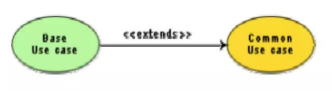
The main idea behind the extends relationship among the use cases is that it allows you to show optional system behavior. An optional system behavior is extended only under certain conditions. This relationship among use cases is also predefined as a stereotype as shown in fig. 7.7. The extends relationship is similar to generalization. But unlike generalization, the extending use case can add additional behavior only at an extension point only when certain conditions are satisfied. The extension points are points within the use case where variation to the mainline (normal) action sequence may occur. The extends relationship is normally used to capture alternate paths or scenarios.
Example use case extension
Organization of use cases
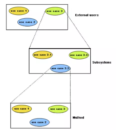
When the use cases are factored, they are organized hierarchically. The high-level use cases are refined into a set of smaller and more refined use cases. Top-level use cases are super-ordinate to the refined use cases. The refined use cases are sub-ordinate to the top-level use cases. Note that only the complex use cases should be decomposed and organized in a hierarchy. It is not necessary to decompose simple use cases. The functionality of the super-ordinate use cases is traceable to their sub-ordinate use cases. Thus, the functionality provided by the super-ordinate use cases is composite of the functionality of the sub-ordinate use cases. In the highest level of the use case model, only the fundamental use cases are shown. The focus is on the application context. Therefore, this level is also referred to as the context diagram. In the context diagram, the system limits are emphasized. In the top-level diagram, only those use cases with which external users of the system. The subsystem-level use cases specify the services offered by the subsystems. Any number of levels involving the subsystems may be utilized. In the lowest level of the use case hierarchy, the class-level use cases specify the functional fragments or operations offered by the classes.
Hierarchical organization of use cases

Comments are closed