Digital Modulation provides more information capacity, high data security, quicker system availability with great quality communication. Hence, digital modulation techniques have a greater demand, for their capacity to convey larger amounts of data than analog ones.
There are many types of digital modulation techniques and we can even use a combination of these techniques as well. In this chapter, we will be discussing the most prominent digital modulation techniques.
Amplitude Shift Keying
The amplitude of the resultant output depends upon the input data whether it should be a zero level or a variation of positive and negative, depending upon the carrier frequency.
Amplitude Shift Keying (ASK) is a type of Amplitude Modulation which represents the binary data in the form of variations in the amplitude of a signal.
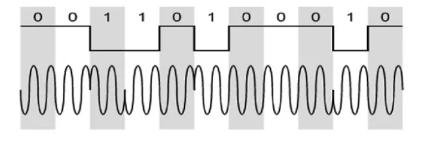
Following is the diagram for ASK modulated waveform along with its input.
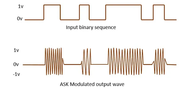
Any modulated signal has a high frequency carrier. The binary signal when ASK is modulated, gives a zero value for LOW input and gives the carrier output for HIGH input.
Frequency Shift Keying
The frequency of the output signal will be either high or low, depending upon the input data applied.
Frequency Shift Keying (FSK) is the digital modulation technique in which the frequency of the carrier signal varies according to the discrete digital changes. FSK is a scheme of frequency modulation.
Following is the diagram for FSK modulated waveform along with its input.
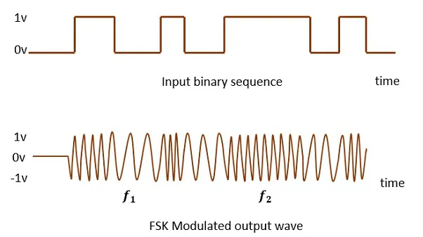
The output of a FSK modulated wave is high in frequency for a binary HIGH input and is low in frequency for a binary LOW input. The binary 1s and 0s are called Mark and Space frequencies.
Phase Shift Keying
The phase of the output signal gets shifted depending upon the input. These are mainly of two types, namely BPSK and QPSK, according to the number of phase shifts. The other one is DPSK which changes the phase according to the previous value.
Phase Shift Keying (PSK) is the digital modulation technique in which the phase of the carrier signal is changed by varying the sine and cosine inputs at a particular time. PSK technique is widely used for wireless LANs, bio-metric, contactless operations, along with RFID and Bluetooth communications.
PSK is of two types, depending upon the phases the signal gets shifted. They are −
Binary Phase Shift Keying (BPSK)
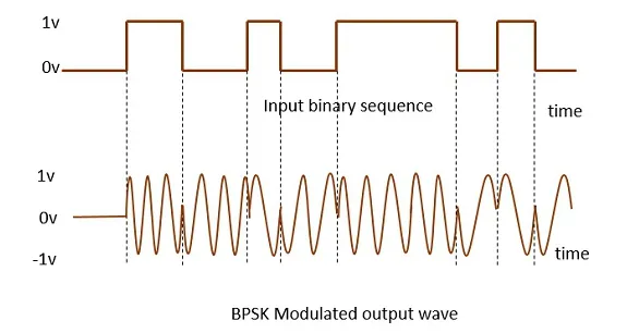
This is also called as 2-phase PSK (or) Phase Reversal Keying. In this technique, the sine wave carrier takes two phase reversals such as 0° and 180°.
BPSK is basically a DSB-SC (Double Sideband Suppressed Carrier) modulation scheme, for message being the digital information.
Following is the image of BPSK Modulated output wave along with its input.
Quadrature Phase Shift Keying (QPSK)
This is the phase shift keying technique, in which the sine wave carrier takes four phase reversals such as 0°, 90°, 180°, and 270°.
If this kind of techniques are further extended, PSK can be done by eight or sixteen values also, depending upon the requirement. The following figure represents the QPSK waveform for two bits input, which shows the modulated result for different instances of binary inputs.
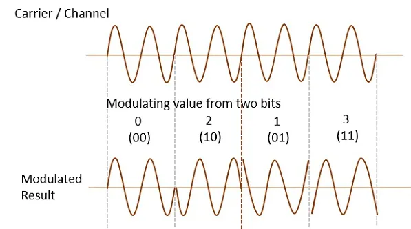
QPSK is a variation of BPSK, and it is also a DSB-SC (Double Sideband Suppressed Carrier) modulation scheme, which send two bits of digital information at a time, called as bigits.
Instead of the conversion of digital bits into a series of digital stream, it converts them into bit-pairs. This decreases the data bit rate to half, which allows space for the other users.
Differential Phase Shift Keying (DPSK)
In DPSK (Differential Phase Shift Keying) the phase of the modulated signal is shifted relative to the previous signal element. No reference signal is considered here. The signal phase follows the high or low state of the previous element. This DPSK technique doesn’t need a reference oscillator.
The following figure represents the model waveform of DPSK.
It is seen from the above figure that, if the data bit is LOW i.e., 0, then the phase of the signal is not reversed, but is continued as it was. If the data is HIGH i.e., 1, then the phase of the signal is reversed, as with NRZI, invert on 1 (a form of differential encoding).
If we observe the above waveform, we can say that the HIGH state represents an M in the modulating signal and the LOW state represents a W in the modulating signal.