
Modulation is an operation of varying amplitude or frequency or phase of carrier signal according to the instantaneous amplitude of the baseband signal/modulating signal.
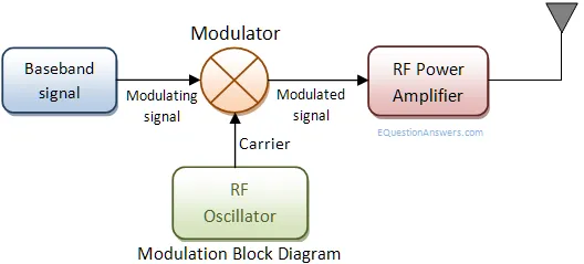
Here baseband signals comes from a audio/video or computer. Baseband signals are also called modulating signal as it modulates carrir signal. Carrier signals are high frequecy radio waves it generally comes from a radio frequency oscillators. These two signls are combined in modulator. Modulator takes the instantenious amplitute of baseband signal and varies amplitute/frequency/phase of carrier signal. Resultant signal is a modulated signal. It goes to an RF-amplifier for signal power boosting and then feed to antenna or a co-axial cable.
There are two types of modulation analog and digital. Analog modulation delas with the voice, video and regular waves of base band signals. Where as digital modulations are with bit streams or symbols from computing vevices as base band signals.
DeModulation:
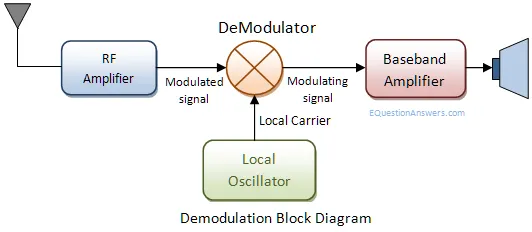
Demodulation is the opposite process of modulation. Modulator is a part of signal transmitter where as demodulator is the receiving side. In broadcast system radio tranmitting station does to modulation part. A radio receiver acts as a demodulator. A modem receives signals and also transmits signals thus it does modulation and demodulation at the same time. Thus the name modem has been given. A radio antenna receives low power signal. A co-axial cable end point can also taken as an signal input. An RF amplifer boosts the signal amplitude. Then the signal goes to a demodulator. demodulator does the reverse of modulation and extracts the backband signal from carrier. Then the base band signal is amplified to feed a audio speaker or video moitor or TTL/CMOS signal levels to match computer inpts.
What is De-modulation?
Demodulation is the opposite process of modulation where the varying amplitude, frequency or phase of carrier signal is extracted to construct the original the message signal.
What are the different types of modulations?
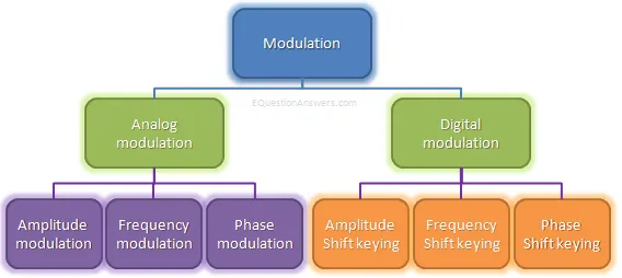
There are mainly two categories of modulations: analog and digital. Here is a diagram showing the types of modulations and further the sub types of analog and digital modulations.
Analog Modulation:
Analog modulation refers to the process of transferring analog low frequency baseband signal, like an audio or TV signal over a higher frequency carrier signal such as a radio frequency band. Baseband signal is always analog for this modulation.
There are three properties of a carrier signal amplitute, frequency and phase thus there are three basic types of analog modulations.
- Amplitude Modulation (AM)
- Frequency Modulation (FM)
- Phase modulation (PM)
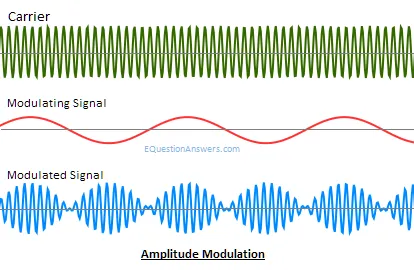
Amplitute Modulation
Amplitude modulation or AM is the process of varying the instantaneous amplitude of carrier signal accordingly with instantaneous amplitude of message signal.
Thus, if m(t) is the message signal and c(t)=Acoswct then AM signal F(t) is written as
F(t)= Acoswct+m(t) coswct
F(t)=[A+m(t)] coswct
AM Advantage
AM is the simplest type of modulation. Hardware design of both transmitter and receiver is very simple and less cost effective.
AM Disadvange:
AM is very susceptible to noise.
Application:
1) AM radio broad cast is an example
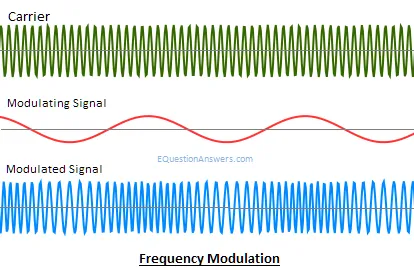
Frequency modulation
FM or Frequency modulation is the process of varying the in instantaneous frequency of Carrier signal accordingly with instantaneous amplitude of message signal. Thus, if m(t) is the message signal and c(t)=Acoswct then FM signal will be
F(t)= Acos(wc t+kf ∫m(α)dα)
FM Advantage
Modulation and demodulation does not catch any channel noise.
FM Disadvange:
Circuit needed for FM modulation and demodulation is bit complicated than AM
Application:
1) FM radio broad cast is an example
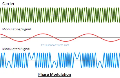
Phase modulation (PM)
PM or Phase modulation is the process of varying the instantaneous phase of Carrier signal accordingly with instantaneous amplitude of message signal. Thus if m(t) is the message signal and c(t)=Acoswct then PM signal will be
F(t)= Acos(wct+kpm(t))
PM Advantage
Modulation and demodulation does not catch any channel noise.
PM Disadvange:
Circuit needed for PM modulation and demodulation is bit complicated than AM and FM
Application:
1) Satellite communication.
Digital modulation:
Analog modulation refers to the process of transferring digital low frequency baseband signal, like digital bitstream from computers over a higher frequency carrier signal such as a radio frequency band. Digital modulation in somewhat similar to the analog modulation except base band signal is of discrete amplitude level. For binary signal it has only two level, either high or logic 1 or low or logic 0. The modulation scheme is mainly three types.
- ASK or Amplitude shift Key
- FSK or Frequency shift key
- PSK or Phase shift key
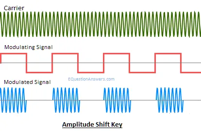
ASK or Amplitude shift Key:
When the carrier signal’s instantaneous amplitude is varied in proportion to message signal m(t). We have the modulated carrier m(t)coswct where coswct is the carrier signal. As the information is an on-off signal the output is also an on-off signal where the carrier is present when information is 1 and carrier is absent when information is 0. Thus this modulation scheme is known as on-off keying (OOK) or amplitude shift key.
Application:
- Used in our infrared remote controls
- Used in fibre optical tranmitter and receiver.
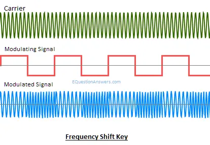
FSK or Frequency shift key:
When Data are transmitted by varying instantaneous frequency of the carrier, we have the case of frequency shift key. In this modulation carrier has two predefined frequency wc1 and wc2. When information bit is 1 carrier with wc1 is transmitted i.e. coswc1 and When information bit is 0 carrier with wc0 is transmitted i.e. coswc0
Application:
- Many modems used FSK in telemetry systems
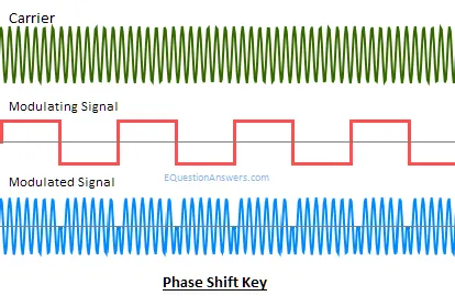
PSK or Phase shift key:
The instantaneous phase of the carrier is shifted for this modulation. If the base band signal m(t) =1 carrier in phase is transmitted. If m(t)=0 carrier with out of phase is transmitted i.e. cos(wct+П). If phase shift is done in 4 different quadrants then 2bit of information can be sent at a time. This scheme is a special case of PSK modulation known as QPSK or Quadrature Phase Shift Key.

Comments are closed