
Single side band suppressed carrier: (SSB-SC)
· In SSB-SC any one of the unwanted side band is suppressed along with the carrier signal.
· Since DSB-FC consumes more power as both the side bands are transmitted and the same information is contained n both side bands one of it can be eleminated.
· Also the bandwidth consmption is more in DSC-FC.
· To overcome all these things one of the side band can be eleminated as it is symmetrical and the information contained in other band will be redundant.
· There are two techniques are used to generate the SSB-SC signal.
1. Filter method.
2. Phase shift method.
1.Filter method:
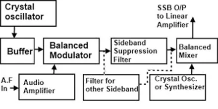
Working of filter method:
· A crystal oscillator produces a stable carrier frequency(fc) signal.
· This carrier frequency is then fed to the balanced modulator through a buffer amplifier which isolates these two satges.
· The audio signal from the modulating amplifier modulates the carrier in the balanced modulator. Audio frequency range is 300 to 2800 Hz.
· The carrier is also suppressed in this stage but allows only to pass the both side bands. (USB & LSB).
· A band pass filter (BPF) allows only a single band either USB or LSB to pass through it. It depends on our requirements.
Let we want to pass the USB then LSB will be suppressed. Inthis case.
fc = 100 KHz
Audio range = 300 – 2800 Hz
USB frequency range = fc + 300 to fc + 2800
= 100000 + 300 to 100000 + 2800
= 100300 to 102800 Hz
So this band of frequency will be passed on through the USB filter section
· The frequency of the SSB signal generated at output of filter is very low as compared to transmitter frequency.
· The frequency is boosted up to the transmitter frequency by balance mixer and crystal oscillator.
· This process of frequency boosting is also called as up conversion.
· The SSB signal havng frequency equal to the transmitter frequency is then amplified by the linear amplifiers.
2.Phase shift method:
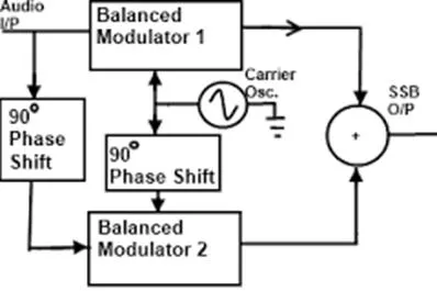
Working of phase shift method:
· It uses two balanced modulators instead of one.
· The balanced modulators effectively eliminate the carrier.
· The carrier oscillator is applied directly to the upper balanced modulator along with the audio modulating signal.
· Then both the carrier and modulating signal are shifted in phase by 90oand applied to the second, lower, balanced modulator.
· The two balanced modulator output are then added together algebraically.
· The phase shifting action causes one side band to be canceled out when the two balanced modulator outputs are combined
Mathematical analysis:
Input of BM1 are, sin wmt and sin (wct +90 ̊ )
Therefore output of BM1= sin (wct +90 ̊ ) sin wmt
= cos (wct +90 ̊ – wmt) – cos (wct +90 ̊ + wmt)
LSB 90 ̊ phase shift USB 90 ̊ phase shift
Input of BM2 are, sin wct and sin (wmt +90 ̊ )
Therefore output of BM2= sin (wmt +90 ̊ ) sin wct
= cos (wct- wmt -90 ̊ ) – cos (wct+ wmt +90 ̊ )
LSB -90 ̊ phase shift USB 90 ̊ phase shift
Output of summing amplifier,
= cos (wct +90 ̊ – wmt) – cos (wct +90 ̊ + wmt) + cos (wct- wmt -90 ̊ ) – cos (wct+ wmt +90 ̊ )
· One of the side band is suppressed.
The advantages of single side band SSB transmission:
1. It allows better management of the frequency spectrum. More transmission can fit into a given frequency range than would be possible with double side band DSB signals.
2. All of the transmitted power is message power none is dissipate as carrier power.
3. The noise content of a signal is an exponential function of the bandwidth: the noise will decrease by 3dB when the bandwidth is reduced by half. There fore, single side band SSB signals have less noise contamination than DSB double side band.
Disadvantages:
1. The cost of a single side band SSB reciver is higher than the double side band DSB counterpart be a ratio of about 3:1.
2. The average radio user wants only to flip a power switch and dial a station. Single side band SSB recievers require several precise frequency control settings to minimize distortion and may require continual readjustment during the use of the system.
Advantages of amplitude modulation:
· Noise reduction.
· Increase the system fidelity.
· Efficient use of power.
Disadvantages:
· Low transmission power efficiency.
· Poor quality reception.
· Noisy signal reception.
· Limited operating radio range.
· Complex circuits.
Applications:
· Medium and high frequency bands for long-distancet radio broadcast applications.
· Two way mobile radio communication.
· Point to point long distant telephony(SSB).
· VSB(television app).

Comments are closed