
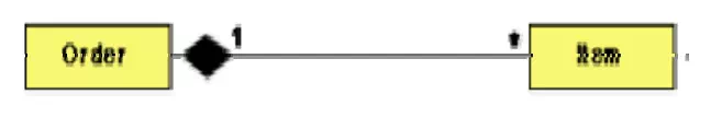
Composition is a stricter form of aggregation, in which the parts are existence-dependent on the whole. This means that the life of the parts closely ties to the life of the whole. When the whole is created, the parts are created and when the whole is destroyed, the parts are destroyed. A typical example of composition is an invoice object with invoice items. As soon as the invoice object is created, all the invoice items in it are created and as soon as the invoice object is destroyed, all invoice items in it are also destroyed. The composition relationship is represented as a filled diamond drawn at the composite-end. An example of the composition relationship.
Representation of composition
Association vs. Aggregation vs. Composition
• Association is the most general (m:n) relationship. Aggregation is a stronger relationship where one is a part of the other. Composition is even stronger than aggregation, ties the lifecycle of the part and the whole together.
• Association relationship can be reflexive (objects can have relation to itself), but aggregation cannot be reflexive. Moreover, aggregation is anti-symmetric (If B is a part of A, A cannot be a part of B).
• Composition has the property of exclusive aggregation i.e. an object can be a part of only one composite at a time. For example, a Frame belongs to exactly one Window whereas in simple aggregation, a part may be shared by several objects. For example, a Wall may be a part of one or more Room objects.
• In addition, in composition, the whole has the responsibility for the disposition of all its parts, i.e. for their creation and destruction.
· in general, the lifetime of parts and composite coincides
· parts with non-fixed multiplicity may be created after compositing itself
· parts might be explicitly removed before the death of the composite
For example, when a Frame is created, it has to be attached to an enclosing Window. Similarly, when the Window is destroyed, it must in turn destroy its Frame parts.
Inheritance vs. Aggregation/Composition
• Inheritance describes ‘is a’ / ‘is a kind of’ relationship between classes (base class – derived class) whereas aggregation describes ‘has a’ relationship between classes. Inheritance means that the object of the derived class inherits the properties of the base class; aggregation means that the object of the whole has objects of the part. For example, the relation “cash payment is a kind of payment” is modeled using inheritance; “purchase order has a few items” is modeled using aggregation. Inheritance is used to model a “generic-specific” relationship between classes whereas aggregation/composition is used to model a “whole-part” relationship between classes.
• Inheritance means that the objects of the subclass can be used anywhere the super class may appear, but not the reverse; i.e. wherever we could use instances of ‘payment’ in the system, we could substitute it with instances of ‘cash payment’, but the reverse cannot be done.
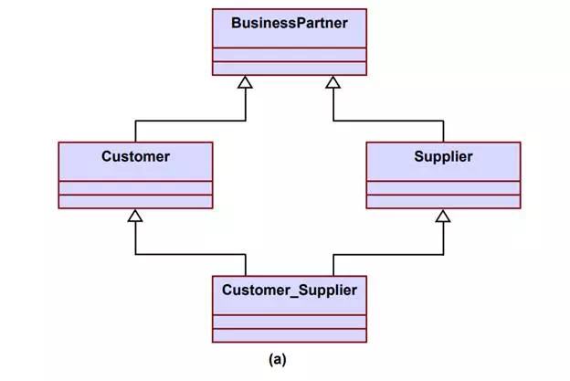
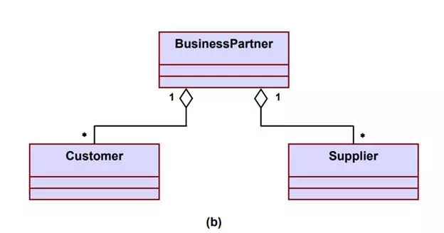
• Inheritance is defined statically. It cannot be changed at run-time. Aggregation is defined dynamically and can be changed at run-time. Aggregation is used when the type of the object can change over time. For example, consider this situation in a business system. A Business Partner might be a Customer or a Supplier or both. Initially we might be tempted to model it. But in fact, during its lifetime, a business partner might become a customer as well as a supplier, or it might change from one to the other. In such cases, we prefer aggregation instead. Here, a business partner is a Customer if it has an aggregated Customer object, a Supplier if it has an aggregated Supplier object and a “Customer Supplier” if it has both. Here, we have only two types. Hence, we are able to model it as inheritance. But what if there were several different types and combinations thereof? The inheritance tree would be absolutely incomprehensible. Also, the aggregation model allows the possibility for a business partner to be neither – i.e. has neither a customer nor a supplier object aggregated with it.
• The advantage of aggregation is the integrity of encapsulation. The operations of an object are the interfaces of other objects which imply low implementation dependencies. The significant disadvantage of aggregation is the increase in the number of objects and their relationships. On the other hand, inheritance allows for an easy way to modify implementation for reusability. But the significant disadvantage is that it breaks encapsulation, which implies implementation dependence.
Representation of Business Partner, Customer, Supplier relationship (a) using inheritance (b) using aggregation
Interaction Diagrams
Interaction diagrams are models that describe how group of objects collaborate to realize some behavior. Typically, each interaction diagram realizes the behavior of a single use case. An interaction diagram shows a number of example objects and the messages that are passed between the objects within the use case.
There are two kinds of interaction diagrams: sequence diagrams and collaboration diagrams. These two diagrams are equivalent in the sense that any one diagram can be derived automatically from the other. However, they are both useful. These two actually portray different perspectives of behavior of the system and different types of inferences can be drawn from them. The interaction diagrams can be considered as a major tool in the design methodology.
Sequence Diagram
A sequence diagram shows interaction among objects as a two-dimensional chart. The chart is read from top to bottom. The objects participating in the interaction are shown at the top of the chart as boxes attached to a vertical dashed line. Inside the box the name of the object is written with a colon separating it from the name of the class and both the name of the object and the class are underlined. The objects appearing at the top signify that the object already existed when the use case execution was initiated. However, if some object is created during the execution of the use case and participates in the interaction (e.g. a method call), then the object should be shown at the appropriate place on the diagram where it is created. The vertical dashed line is called the object’s lifeline. The lifeline indicates the existence of the object at any particular point of time. The rectangle drawn on the lifetime is called the activation symbol and indicates that the object is active as long as the rectangle exists. Each message is indicated as an arrow between the lifeline of two objects. The messages are shown in chronological order from the top to the bottom. That is, reading the diagram from the top to the bottom would show the sequence in which the messages occur. Each message is labeled with the message name. Some control information can also be included. Two types of control information are particularly valuable.
• A condition (e.g. [invalid]) indicates thhat a message is sent, only if the condition is true.
• An iteration marker shows the message is sent many times to multiple receiver objects as would happen when a collection or the elements of an array are being iterated. The basis of the iteration can also be indicated e.g. [for every book object].
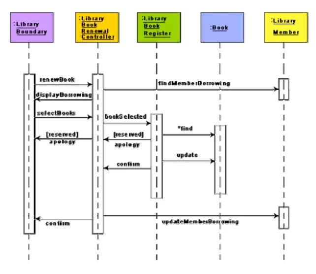
The sequence diagram for the book renewal use case for the Library Automation Software. The development of the sequence diagram in the development methodology would help us in determining the responsibilities of the different classes; i.e. what methods should be supported by each class.
Sequence diagram for the renew book use case
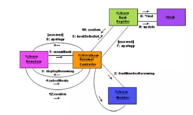
Collaboration Diagram
A collaboration diagram shows both structural and behavioral aspects explicitly. This is unlike a sequence diagram which shows only the behavioral aspects. The structural aspect of a collaboration diagram consists of objects and the links existing between them. In this diagram, an object is also called a collaborator. The behavioral aspect is described by the set of messages exchanged among the different collaborators. The link between objects is shown as a solid line and can be used to send messages between two objects. The message is shown as a labeled arrow placed near the link. Messages are prefixed with sequence numbers because they are only way to describe the relative sequencing of the messages in this diagram. The use of the collaboration diagrams in our development process would be to help us to determine which classes are associated with which other classes.
Collaboration diagram for the renew book use case s

Comments are closed