
Interaction models shows the interaction between the components of a system, or between the system being developed and other systems (or users).
· Modeling user interaction is important as it helps to identify user requirements.
· Modeling system to system highlights the communication problems that may arise.
· Modeling component interaction helps us understand if the proposed system structure is likely to deliver the required non-functional requirements.
We’re going to cover user case and sequence diagrams. Each present the interactions at different level of detail.
1. Use case diagram mostly use to model the interactions between system and external actors (users or other systems).
2. Sequence diagram are used to model interactions between system components.
Use Case Diagram
The use case diagram is widely used to support requirements elicitation.
We’ve covered the user case diagram along with scenarios in detail in Requirements Elicitation & Analysis.
Sequence Diagram
Sequence diagrams are primarily used to model the interactions between the users and the objects in the system, and between the object themselves.
It’s used to give an overview of a specific parts of the system, a specific use case, actually the important ones, or the unclear parts of the system. So, you don’t have to sketch out every single interaction in the system.
It’s worth mentioning that it either shows generic form or a specific form of a use case. A generic form shows all possible sequence of interactions to all the scenarios (conditions) of a use case, while a specific form shows the sequence of interactions of one scenario.
Furthermore, we may end up with going back to your class diagram, and start refine, or adding new classes.
Here is an example on the sequence diagram. We’ll go through each part of it.
Syntax
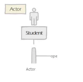
Actors
Describe the users or other system that are involved in the interactions.
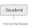
Horizontal Boxes
Represents the participating objects.
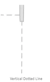
Vertical Dotted Lines
Represents the time, the life-line, or the existence of an object over a certain period of time. It increases as we go down.
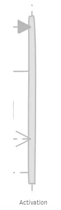
Rectangular Box on the life-line
Represents an activation of an object. It’s the time period during which the object performs an operation.
So, the life-line just denotes the object existence, while activation denotes the object is performing operation as well.
Messages
Objects communicate and interact with each other by sending messages. It could be a method call, or returned value.
Message could be read from the left to right, or, from right to left. But, life-line is from top to the bottom.
Method Call
It could be a method call to the receiving object. This sketched by drawing a solid arrow from the caller object to the receiving object. The method call is done during the life-line of the caller object.
This mostly denotes that there is a relationship between the caller object, and the receiving one. And so the caller object can trigger any public method defined in the receiving object class.

Method Call
You can add a condition on the arrow says that this message won’t be sent unless the condition is true.

Condition
When arrow points to an object box, this means a new instance of this object will be created.
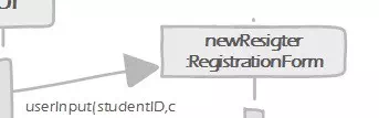
New Instance
Returned Value
When you are expecting a response, dashed arrow (stick head) represents the returned value. Only show the dashed arrow (stick head) if it’s important.

Returned Value
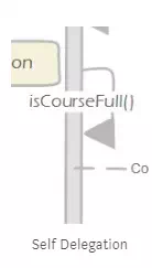
Self Delegation
An operation or a method within the same object’s class.

Comments are closed